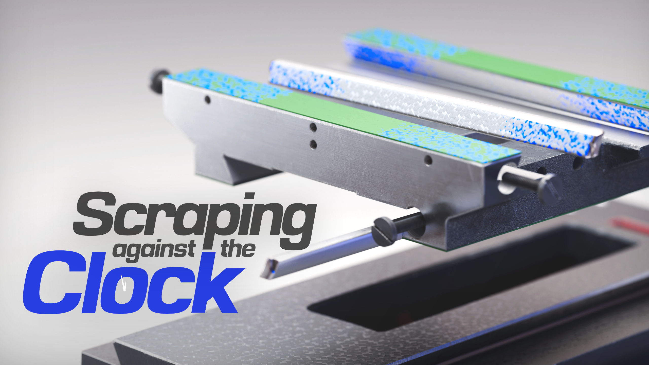
Marcus is a local expert on scraping, and we've got him showing us exactly what to do to bring a hobby grade mill up to professional spec. To start, we're reconditioning the MH28V mill table.
I walked into Marcus’s shop one day where he was running scraping classes, and one of the students — a person I’ve never met before — turns to me and the first thing he says is “so when’s the scraping video coming out? This video took about 10 months to complete. I first met Marcus because he offered to help after seeing my previous video on the build project. We actually finished scraping the machine table in late 2022 and I was planning to put the whole machine’s scraping work in one big video, but it eventually became obvious that it would take too long to make and the video would be too big and complicated, so now it’ll be a series broken up by roughly each casting piece, starting with the mill table.
For the uninitiated, this article is an accompaniment to my YouTube video (link above in purple) which is part of an project to thorough recondition an Optimum MH28V hobby milling machine to a 5 axis CNC. The whole process will be documented in detail.
I don’t want to make the focus of these videos and articles about introducing scraping to the completely uninitiated, but more for those who might have fiddled at home once or have just watched some videos and would like to know more or do a project of their own. First I’ll explain a bit about why you’d want to use scraping, and then move on to talking about the specific process of scraping my machine table.
I tend to look at scraping in a similar light to die making — specifically when those artisans match up polished surfaces to produce a perfect transition between two plastic moulded parts. Apple products use this all the time to a masterful degree when they’re not just machining whole computer chassis’ out of aluminium. Scraping is an uncommon skill that takes a trained hand for creating very precise results. It’s really cool, because you can use it make very high quality machinery with fairly simple equipment. The hardest part is having a large enough surface plate and the time and skill to get what you want out of it.
Scraping is an old practice of using a simple hand tool with a single sharp edge to scrape away very small amounts of material until the whole surface matches the reference surface. Usually that reference surface is a flat surface plate, and hence, usually the goal of scraping is to make a flat surface, but that’s not always the case. Sometimes you just want to make one casting rigidly mate with another casting. The most relevant application of this is mating the mill column with the base. You can use scraping to finely adjust squareness and then slowly match up the two surfaces to get as many contact points as practically possible. The more contact points, the more rigid the joint, but this case has little care for how flat the two surfaces are.


Notice the super rough disc grinding on the column. These are the kind of shortcuts that these Chinese hobby manufacturers take to get machines cheap enough for the market’s demands. This will be completely resurfaced by scraping in a future video, and we probably won’t scrape the base as that’s got a decently machined reference surface. This will all be covered in a future video and article.
The way to tell where the two parts are making contact is by applying engineer’s blue to one of the surfaces and carefully rubbing the two together. Where blue transfers to the other part is where contact was made (as long as you’ve applied an appropriate amount of blue and not just flooded the whole area).


The result:

Those blue high spots are where you want to scrape material away to gradually bring the surface in closer agreement with the reference surface.
The scraper can take many forms depending on the task at hand, but by far the most common scraper will look like this:


Here’s some closeups of the carbide insert. For cast iron, the cutting edge has a -5 degree rake angle, and there is a cutting edge on both sides so once one side gets dull, you can just use the other side.

The edge is ground with a particular radius. Start with a larger radius (135mm) and as you approach finishing you’ll usually go to a smaller radius. If you look closely at the scraper above with the red handle, you’ll notice a smaller, tighter radius — good for Moore scraping. (Side note, others call Moore scraping English Bedding Curls).

The brighter spots around the middle are areas that have been scraped. It can be pretty hard to target such small patches, I often miss them, making the valleys deeper and giving myself more work. :(

The above was my attempt at pull scraping. That surface was treated with many different styles of scrape while Marcus was teaching, so it’s a little chaotic. To thank you for reading my articles, here’s a sneak peak at my more refined pull scraping on the mill base flat way.

It’s interesting how rough scraping looks when it’s actually quite smooth (though smoothness isn’t actually the goal either, more on that next). You can see how the blue is very thin and smeared on this print, suggesting that the pull scraping with the large radius grind on the carbide makes a very smooth surface compared to the prints further above.

What was that about smoothness? Well surface grinding makes a very flat AND smooth surface, which is great for many applications, but there are cases where scraping is preferable; and they extend beyond just surface smoothness.
Firstly on the smoothness: machine slideways need oil to move, right? If two very smooth, ground surfaces are used as slideways, they will quickly squeeze all the oil out and surface tension (or something like that…) will just bind them in place. This is where scraping wins out: scraping is good because of the slight valleys it leaves. The below image is an exaggerated example of the surface smoothness of a scraped slideway. The shiny flat plataues are produced using precision ground stones that you use to knock off the small high spots after scraping. Now you have a surface which has patches of flat which are all very flat relative to each other. The valleys leave space for the oil to ‘crawl’ around without ever being completely squeezed out.


When two scraped surfaces are brought together, you get patches of contact surrounded by oil that keeps all the contact points well oiled.

Other benefits to scraping are that it doesn’t require any significant pressure on the part to hold it in place while being worked on, and scraping doesn’t produce heat that warps the part.
A surface grinder usually uses a magnetic chuck to hold that part, exerting force through it and potentially flexing. When the magnet is released, the part can relax back to neutral position, leaving the surface that was flat, now bowed.


Additionally, while grinding, heat is unevenly sunken into the part, causing the top surface to expand, bowing the part up in the middle.


The operator will continue to grind until the surface stabilises and remains flat while grinding.


They call the part done and take it out of the grinder. The part cools down, causing what was flat to become warped into a concave.
Scraping doesn’t need any work holding unless it’s a small piece that will slide around, but that’s still easy to avoid warping the part with.
To start reworking the table of my mill, we first stripped it down completely — removing all screws, brackets and fittings. The first surface to receive attention was the top surface. We started with a pivot and twist test.
A pivot test involves placing the table with the working surface down on the inspection/surface plate — a surface known to be adequately flat. You can then slide one far end of the table back and forth a centimetre or so and watch for where the table pivots from.

If the surface is twisted, it’ll clearly pivot from a far corner. Be careful when diagnosing twist, maybe the whole surface has a gradual twist, or maybe the surface is mostly quite good and you just have a small hump on one corner. This can easily happen if the corner has received a knock or has a burr.

If the surface is convex (a hump in the middle), it’ll spin easily from the centre.

If it’s concave (void in the centre) you’re a little lucky. If you’re going to be roughing, you want a concave so the part can be stabilised and brought into good flatness. Be aware that you can — and probably will — have a combination of concave/convex and twist.
If you have a convex surface, it can dramatically throw off your prints and keep you chasing your tail. A convex (hump in the middle) can be rolled around, causing a larger area to print up than what should.
A convex surface might initially print like this when placed down perfectly evenly.

If you press down on the right side, the surface will roll over leaving printing there.

Continue that around the whole surface…

…and eventually could have yourself convinced that the whole surface is very flat!

The ideal starting point for roughing in a surface is a concave (besides an already flat surface, of course), this eliminates the chance of producing such a false print as above. On my table, the surface looked like this from the factory.
How it printed:

How it would look as a height map:
.png)
It seems that the surface would suffer from the concavity due to the heat cycle of grinding as explained above, but this big high area to the centre right seems to have been an issue with the surface grinder they used in China. So according to Marcus’s expert guidance, we violently roughed out a bunch of material in the centre area plus a little on the left corner to immediately get the surface into a positive concave.
.png)

From there we have a good base or as Marcus says “the surface is stabilised”. From there you can start carefully roughing out the sides to eventually bring the whole surface into an averaged flat.
.png)

.png)

There’s what I feel is two major modes of intent in the scraping we’ve done in this job.: roughing and finishing.
Roughing involves laying down large and long scrapes to blanket whole high spots. For example, the whole general region that blue printed on the previous image would be scraped quite aggressively. The aim is to remove lots of material to get the average of the surface to be flat but you will get large voids between contact points.
Finishing involves calming down and targeting each individual blue spot. You’re now aiming to increase the number of contact points be carefully knocking of the peaks, exposing the surface around each point to make contact. A contact density of 40PPI was the phrase Marcus used most — that is, 40 individual blue spots inside 1 square inch of surface area. This takes time and we often didn’t get to this point as it’s just a small Chinese machine.

.png)


Now with the top surface finished (enough), we flipped the table over to get the flat ways parallel with the top surface. To start, we placed the table with the nice new top surface face-down on the surface plate and ran an indicator on a sled across the flat ways. This gives a very accurate reading on the flatness and parallelism relative to the scraped top surface. It can also be used to check how coplanar the flat ways are to each other, but as we’ll discuss, this not only isn’t important, but actually should not be changed.
So what’s important on the flat ways? Well… as the name suggests, they should indeed be flat, but they only need to be parallel to the top surface running in the long (longitudinal) direction. The image below shows a bad flat way.

Because the table travels along this axis, you need the flat ways to be parallel to the top surface of the table or else that top surface will be misaligned to the motion of the X axis. And don’t think that you’ll just tram the column or spindle to suit, it doesn’t work like that.
Here’s an exaggerated example of what happens when these flat ways our out of parallel with the top surface. Tramming the spindle into that angle doesn’t stop the Z/vertical position of the endmill from changing relative to the table surface.

What isn’t important in the flat ways? Well you don’t need them to be parallel to the top surface in the perpendicular direction to the above case. You can literally have them looking like the image below and still be very functional.

The same goes for getting each flat way coplanar or ‘level’ with each other. The following is perfectly acceptable.

So why is this so forgiving? Well none of these details have any effect on the way these flatways travel along their X axis motion. The saddle is what mates to these flat ways, and you just scrape the saddle to suit whatever you’ve got on the table.
It’s very likely that your machine will be misaligned in both of the mentioned ways. But the manufacturer would have matched the saddle up so that the final geometry of the table came within spec. If you adjust the height of your flat ways to be coplanar, your table top surface will now have an incline such that when you move the Y axis, the effective Z position will change.
Next, we turned to the back face.

This face is never used during machine operation, it’s purely used as a reference both for squaring up the dovetails and as a nice square edge to quickly align work to when doing setups. We didn’t spend time adjusting the alignment of this, we just went straight to making it flat.
Although it’s a very narrow face that you you might start to think of as an edge, it’s still truthfully still a face, so the same approach was taken by removing concavity and then bringing the outer corners in until flat.

It started a little convex, so we roughed out the centre 2/4 and a narrow line in the centre, running its length, resulting in this:


And then continue onto finishing, as usual. At first I was carrying the table over to the surface plate to do print up, then Marcus was kind enough to point out that I can just use one of his straight edges and keep the table in place.

And we’re almost there! All we have left is the dovetails. These are certainly a daunting thought when you don’t have experience. I know I felt that way, but with Marcus’ help, it was pretty easy and quick, we just needed to make a tool for it. The tool looks like this, but we’ll get to that in a minute.

Similar to the flat ways, the dovetails only have certain geometric requirements. The main one we concerned ourselves with was the parallelism of them relative to the long axis of the back face that we scraped earlier.

Hopefully that image explains how the parallelism is important. It must maintain distance from the back face as it travels along the length of the table. To measure that distance, we used the sled tool mentioned above. The sled fits up against the back face and either the flat way or the top face, both should be equally good. A magbase and dial indicator are attached and brought in contact with the dovetail. Now slide the sled carefully along the table, maintaining positive contact with the reference faces, and note the variation. We used this to mark out a basic step scraping topographical.
The angle of the face — the angle which gives the feature its name ‘dovetail’ — is obviously important, but doesn’t have to be so perfect. We didn’t put much effort into measuring and correcting that.
The other major concern is obviously getting the dovetail face flat relative it its angle. So it’s still treated like a face for scraping. But do be able to get in there, you, again, will need a dovetail straight edge.

We even used a bit of step scraping, but it didn’t need much.
From the factory, the dovetails were ground, as you can see. Also notice the +3 written on it, that’s some basic step scraping going on.

We started by doing some basic scrapes to break up the surface to take a decent print.

Pretty quickly the whole surface was rough, but flat, so finishing came next. You can see how that progressed along.


Honestly, I think I should have stopped at the second-to-last one.
You have to be very careful when printing up these dovetail faces as any bias towards one side will dramatically effect the print result, and that’s what I think might have happened on that last one. I doubt I suddenly made a large perfectly flat patch like that, I probably just leaned the straight edge over to that side a bit too much.
The other dovetail needs to be done in a different way — at least in our case. This is because the front face of the table can’t be scraped to make a nice reference face like the back. There’s too many grooves and features that remove surface contact. Instead, we still measured the dovetail’s parallelism relative to the back face, but we did it by placing the table on the surface plate with the back face down. Then put Hoffman rollers in the dovetail and measured the height of the apex of the roller.


So what are Hoffman Rollers and why can’t I just use dowel pins? Dowel pins usually aren’t guaranteed to be round, they can be slightly trilobed. This is fine for their intended use, and when you measure their diameter with a micrometer, it reads correctly at all points, but that’s just an effect of the opposing sides cancelling out their respective errors.

But when that same dowel pin is placed in the a dovetail, the differently angled contact points expose the trilobe effect. This causes uncontrollable variations in your apex measurement. You need to use a gauge pin, or a Hoffman Roller; or rotate the dowel pin while under measurement to find the highest apex producible, and repeat for each spot you measure along the length of the dovetail.

If you can deal with all that measurement trouble, you’re ready to scrape your dovetails into parallelism and flatness. As usual, step scrap if necessary, use a dovetail straight edge, be careful about biased force when printing, and go break something.
Thanks for reading, this video and article were about 10 months in the making due to life commitments and such. Next one might be about scraping the saddle, or maybe I’ll make some random other video in between. Of course, go give the video a watch, signup to the newsletter below, and subscribe on YouTube if you like my pieces of educataining art.